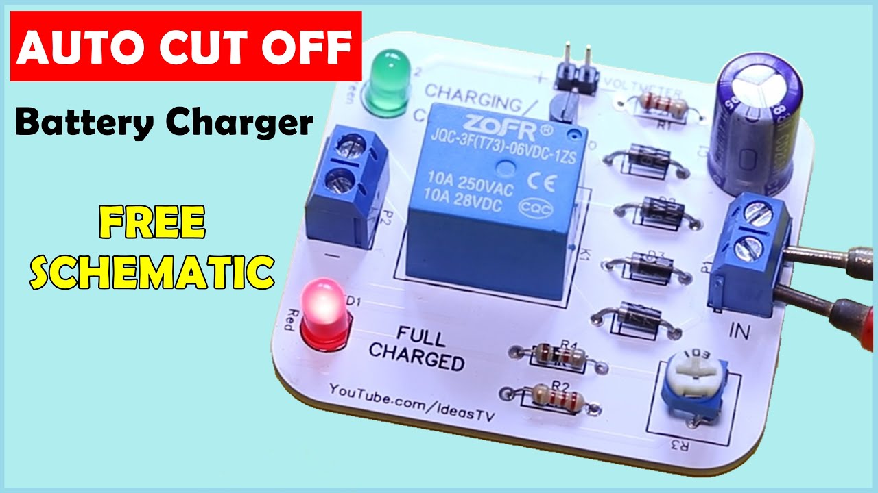
12V Battery Charger Circuit With Auto Cut OFF & ON (PCB Automatic) YouTube
Charging time (for a given current) is ultimately determined by the battery's capacity. For example, a 3300 mAhr smartphone battery will take approximately twice as long to charge as a 1600 mAhr battery, when both are charged using a current of 500 mA.

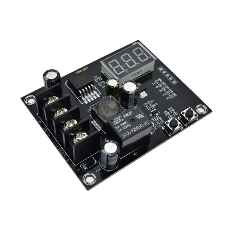
Automatic 12v Battery Charger Circuit Auto Cut OFF & ON TechSaw
The Lithium-Ion Battery Charger Circuit is popular because of its excellent energy density, high cell voltage, and reasonable load characteristics. Everything from small electronic devices, smartphones, and laptops to vehicles now feature lithium chargers.

Liion Battery Charger PCB design glenzac Student Electronics enthusiast Maker
Now here is a 12V, 7Ah smart battery charging circuit which is also referred to as a smart charger uses three-stage of charging i.e. bulk stage, absorption stage, and float stage. You may also like Arduino Controlled 12V battery charger circuit 80% of the charge is done in the bulk stage where the current is constant but voltage is increased.

Review, Teardown Sanyo Eneloop Batteries & Charger NCMQN04A Gough's Tech Zone
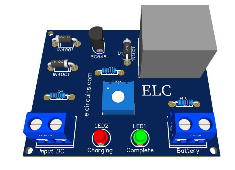
Connect the low-voltage terminals of the transformer to the AC input screw terminal on the PCB board. Connect the battery with the battery screw terminal on the PCB. Be sure you are connecting to the correct polarity. The polarity is marked on the PCB. This charger has no reverse polarity protection, if you connect the battery in the wrong.

12v, 7Ah Smart Battery Charger with PCB Diagram Engineering Projects
We are going to build a simple, low-cost USB powered single cell lithium polymer battery charger as a practical project. Many products integrate lithium polymer batteries. With their high energy density and a vast array of sizes and capacities, you can find the perfect battery to power your circuit.
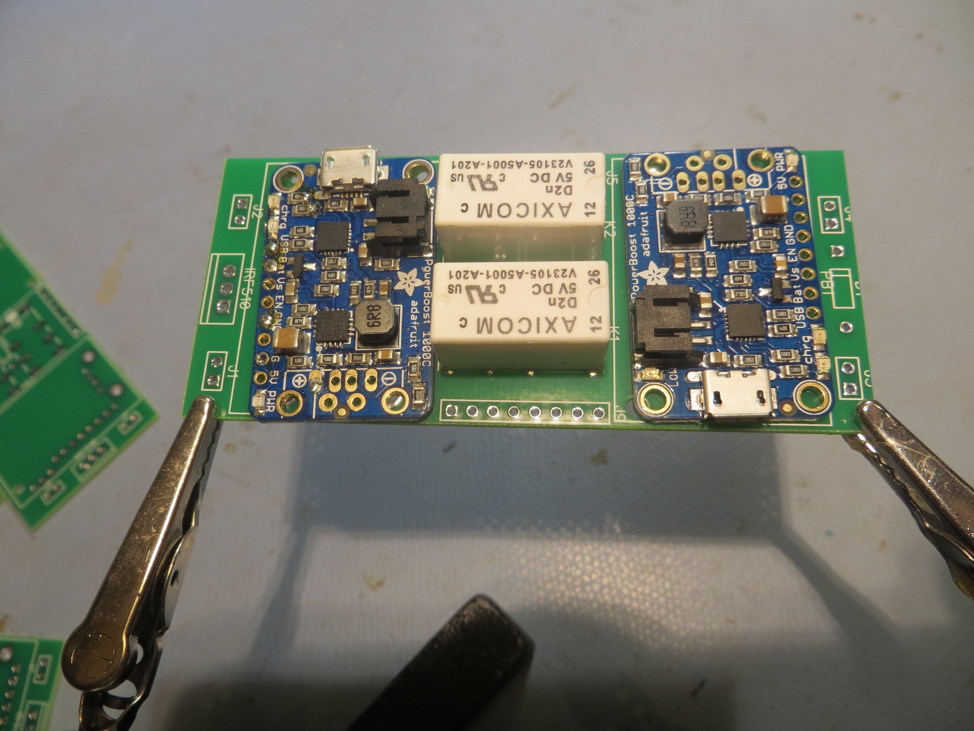
WallE2 Battery Charger PCB Part I Paynter's Palace
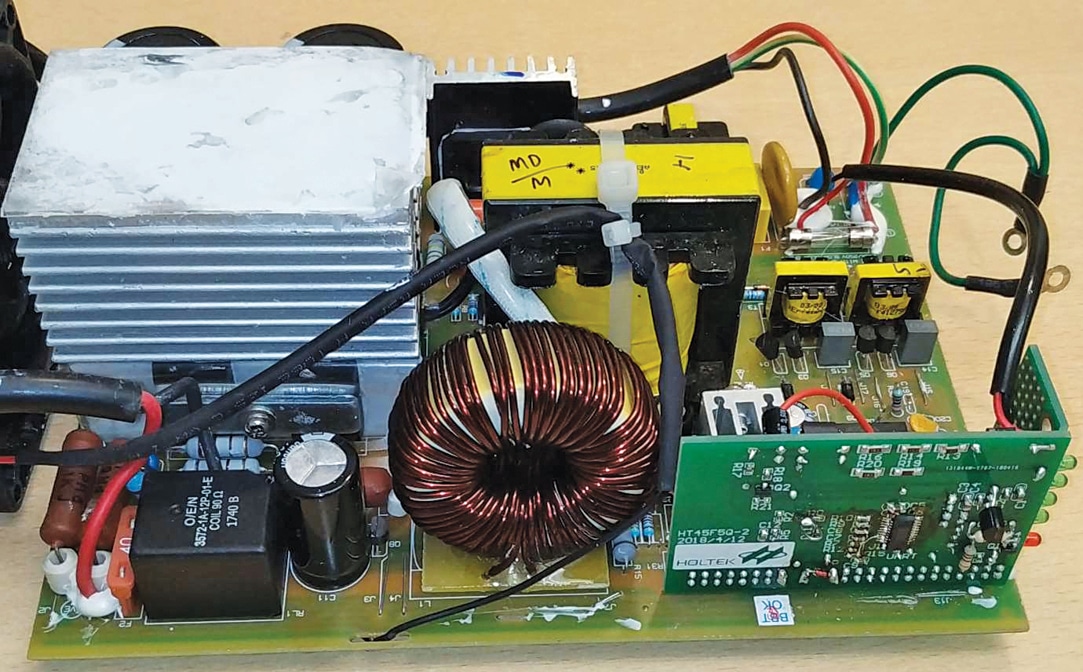
integrated circuit with a switching mode power supply (SMPS) to realize a battery charger. An example of realization of a 12V Nickel-Cadmium battery charger is given. 1 - TSM101 PRESENTATION The TSM101 integrated circuit incorporates a high stability series band gap voltage reference, two ORed operational amplifiers and a current source (Figure 1).

LiIon Battery Charging Protection Circuit Board PCB for Ryobi 20V P108 RB1 C5H9 eBay
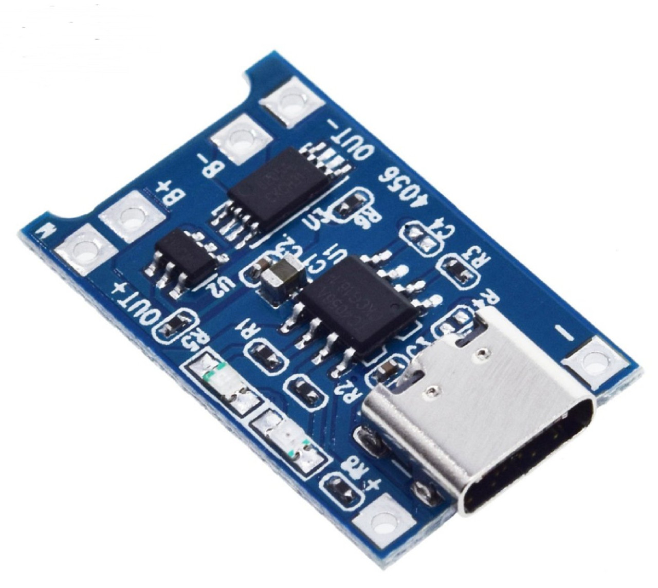
The battery charger circuit is designed around a dedicated lithium-ion battery charger TP4056 IC. TP4056 is a complete constant-current/constant-voltage linear charger for single-cell Lithium-ion batteries. Its SOP package and low external component count make the TP4056 ideally suited for portable applications.
Pcb 12v Battery Charger Circuit Board M10 Pcba Kc338v2.9 Kc337a+ V9 9a Pcb Board Buy Pcb
Battery Chargers are devices that recharge the batteries by putting energy into them. In this project, I will talk about one such battery charger module for charging Lithium Ion Batteries. It is TP4056 Li-Ion Battery Charger. Also read: HOW TO MAKE AN AUTOMATIC BATTERY CHARGER? A Brief Note on TP4056 Lithium Battery Charge Controller
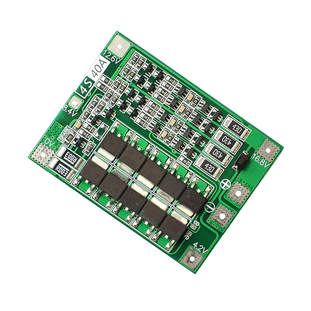
4S 40A Liion Lithium Battery 18650 Charger PCB BMS Protection Board with Balance
Ni-Cd Charger Using a Single Op Amp. Typically, you can use this Ni-Cd circuit to charge standard AA size NiCad batteries. But if you plan to charge NiCad capacity cells, it's ideal to opt for a special charger. And that's because NiCad cells have a meager internal resistance. So, even if you apply a slightly higher voltage, it will.
Simple 12V battery charger with automatic charging indicator + PCB Electronic Circuits
Quick Steps to Make a DIY Battery Charger Circuit. So, here are the quick steps you should take to create a DIY battery charger circuit with power output and emergency power: 1: Build a bridge rectifier by connecting four 1N4007 diodes. 2: Solder the +Ve and -Ve terminals of the bridge rectifier to the secondary winding of the non-C.T transformer.

LiIon Battery Charging Protection Circuit Board PCB for 18V RIDGID R840083 4894836930855 eBay
This lithium battery charger circuit automatically cut off the charging process when the full charge limit of battery is reached (i.e-4.2V) . This circuit also protect our battery from over discharging by automatically cutting the output power when the battery voltage falls below 2.4 volt. TP4056 Chip. The TP4056 is a complete chip for.
Designing Electric Vehicle Charging Solution EV Charger Circuit
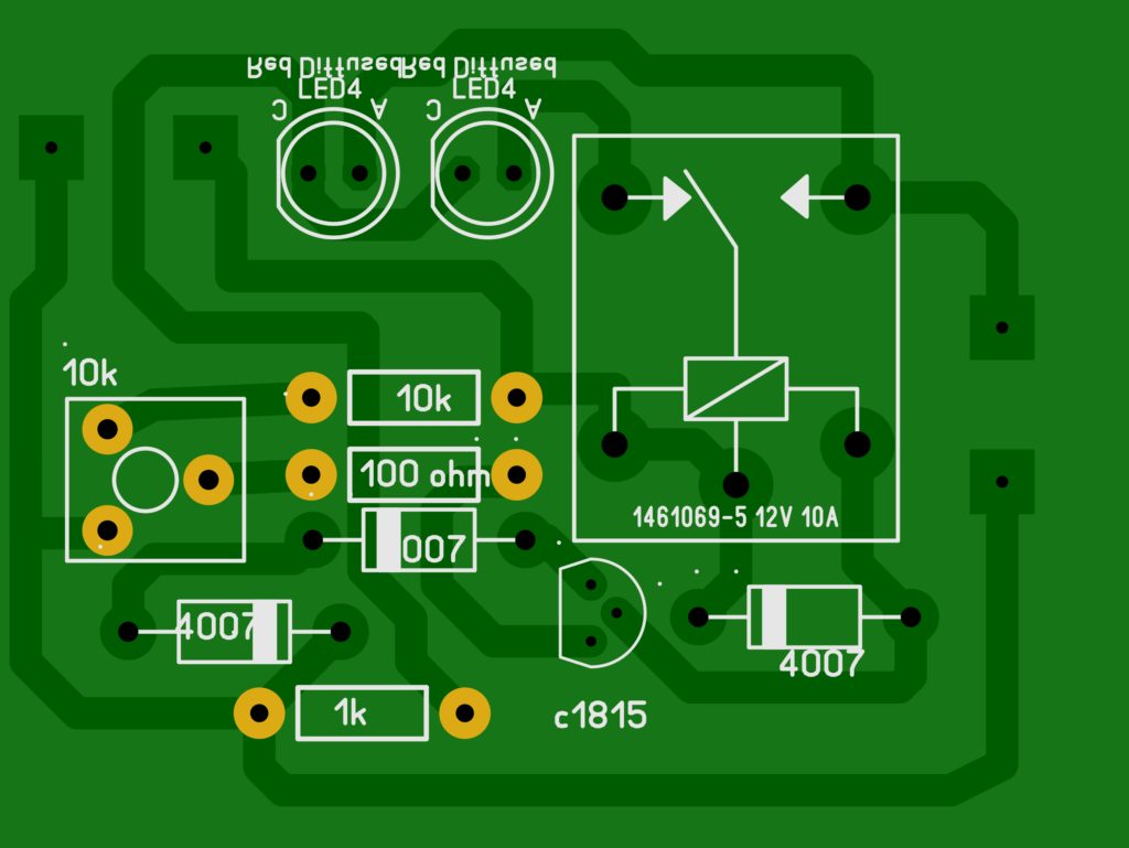
In this section of the guide, we'll cover various battery charge circuit functions and configurations. We will go over the parts and principles for each. 12V Constant Voltage Battery Charger Parts List . To create your constant battery charge circuit for a 12V 100 Ah Battery, you'll need: 10kΩ Resistor x 2 (R1 and R2) 1KΩ Resistor (R3)

a2zteco 12V/24V Lead Acid Battery Smart Charger PCB/Circuit Board DIY Kit, Including Cables and
Basics of battery charging circuit design By Jeff Shepard | June 1, 2021 Charging batteries is simple (in theory) - put a voltage across the terminals and the battery charges. If safe charging, fast charging and/or maximum battery life are important, that's when things get complicated.

MakerFocus 4pcs Dual USB 5V 1A 2.1A 18650 Battery Charger PCB Module B
As the name states, there are three stages in this charger: bulk, absorption, and float. Let's discuss each stage. Bulk Stage About 80% of the battery is charged in the bulk stage. Here, a constant current of 25% of the Ah rating is provided. For example, in the case of 100Ah battery, 25A of constant current is fed and voltage increases with time.
TP4056 Lithium Battery Charger Module with Dual Protection (USBC) CRCibernética
Prevent mistakes by downloading my DESIGN REVIEW CHECKLISTS for the schematic circuit, PCB layout, and enclosure 3D model design: https://predictabledesigns..
12v Automatic battery charger circuit and PCB Soldering Mind
Porcelain for a Tsar, a Maharajah or a King !